Saturday 7 May 2022

QRP Labs QCX Mini - Part 4: a QRP antenna tuner

Now that the QCX Mini and its power pack have been finished, there was only one part still missing: an antenna tuner to match! (pun intended, HI)

Just like the battery pack, the antenna tuner would need to be small, rugged and portable, and not too expensive. You probably know where this is going, don't you?

Yep, this is going to be another report on building the infamous Chinesium 'Manual Days' antenna tuner kit. In my defense, I bought the kit before I knew anything about antenna tuners, so the low price was enough to convince me that this was the kit to buy...

The parts arrived in a cheap plastic bag, and spent a couple of months on a shelf not only waiting for the QCX Mini and its battery pack to be finished, but also for me to learn CW, which is still a daily struggle! Meanwhile, I did read up on the tuner kit, and realized that looking at low cost alone probably wasn't the best way to select an antenna tuner. First of all, the looks of the kit were less than impressive:

A manual antenna tuner doesn't need to be very complicated though. And well, all the parts seemed to be there:

Well the kit was here anyway, so I decided to just give it a try and build it. Not in the original box of course, that thing is just *** Ugly :(
The schematic did not seem to be too complicated, and I calculated (rather optimistically) that the whole thing should be able to fit in a 100x54x30mm box:

A nice and compact enclosure was ordered, and turned this little project into a bit of a challenge. 


Mistakes were made

There's lots of articles on the Internet on this particular kit, and they nearly all mention the terrible build instructions. The complaints seem to mostly focus on the toroid coils, and it's easy to understand why. This is what I found:

  • The small FT37-43 transformer connections are correct in the schematic diagram. However, on some of the circuit boards the wiring is printed in reverse. Please make sure to check this before mounting this part! The 5-turn winding should connect to the 1N60 diode. My PCB (the V 2.0 version) had correct markings though.
  • The larger T106-2 toroid is shown wired in reverse. The 10-turn section should be at the end. The 1-turn section should connect to the variable capacitors. Failing to do so will result in a tuner that's impossible to reach a match on most of the bands.

 It's probably best to carefully check the PCB and building instructions against the schematic (which is correct). There may be other versions with even more mistakes!


The build

First, drill the holes to fit the switches, BNC connectors and variable capacitors:

In this version an analog meter was added. I like to think that it allows for a more accurate SWR reading, although just using the LED also seems to work fine. It did however add to the challenge; I had to cut the PCB to make everything fit!


Winding the toroid coils

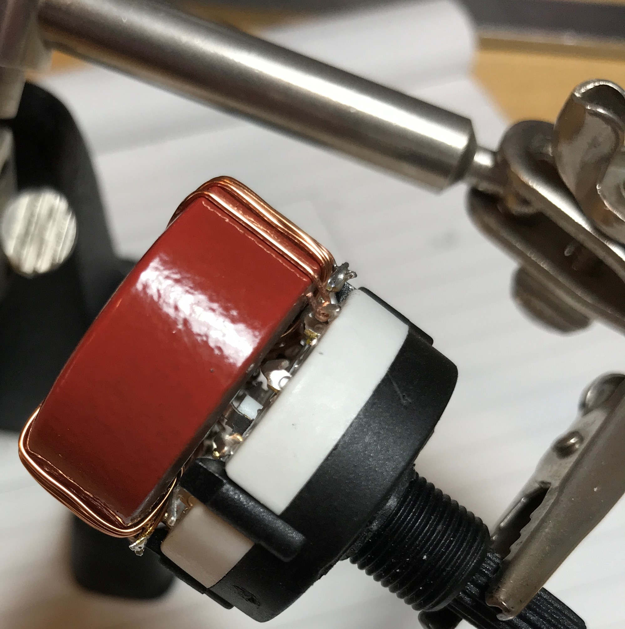
The small FT37-43 coil is quite easy to wind. The larger T106-2 coil is another matter. The original instructions didn't work for me, due to the small size of the enclosure. I decided to go for another approach, which allows me to mount the toroid very close to the rotary switch:

The switch contacts can then be used as hooks to connect the taps:

Here's another closeup:

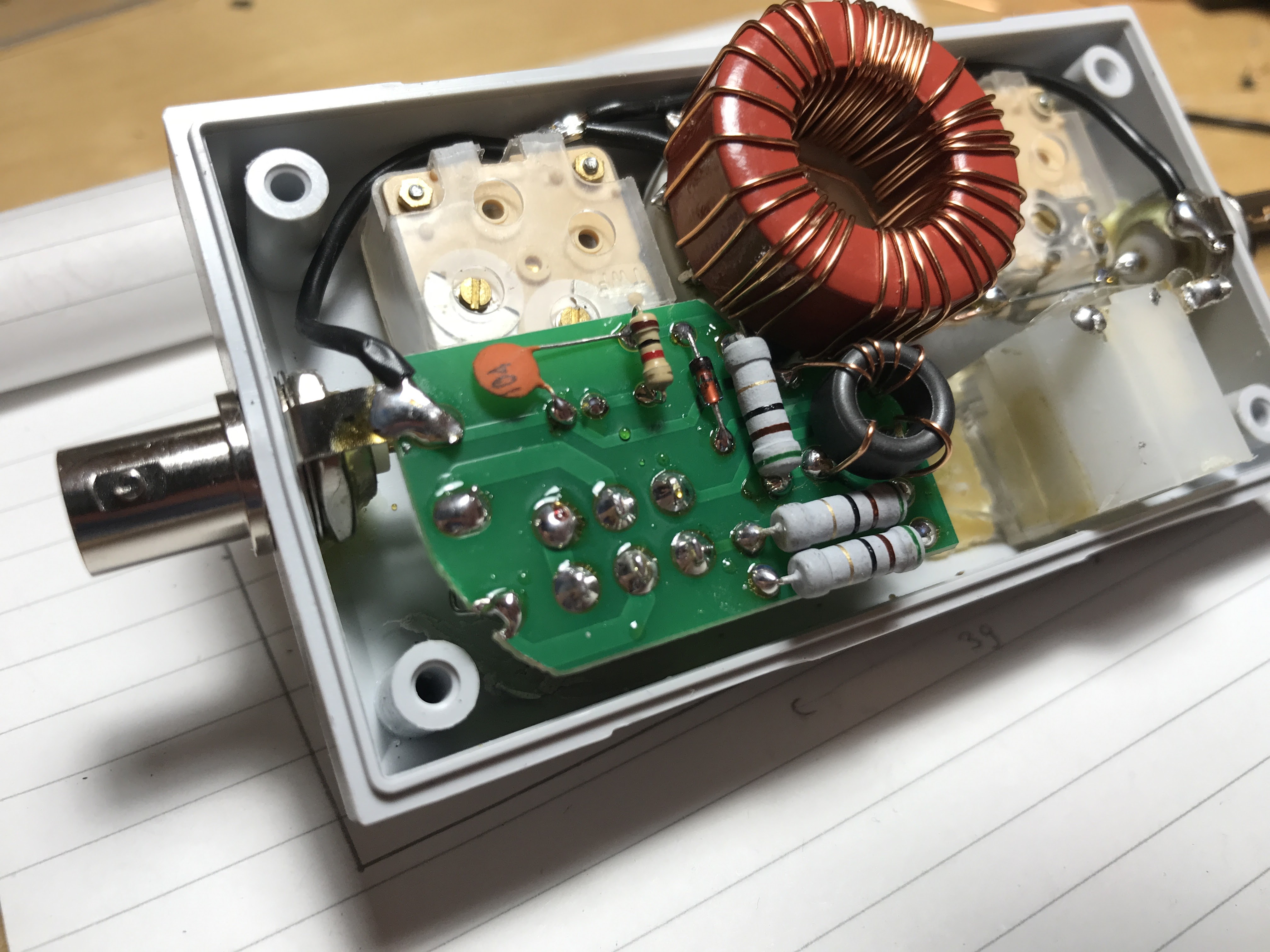
Putting it all together

Using the winding technique shown above I was able to make everything fit into my enclosure. It was a close call though!


The end result

So here's the finished antenna tuner:

Yes I know, it's still no looker. But much to my surprise, it works perfectly well! I'm now able to match my QCX mini to nearly everything that can be used as an antenna (although to be fair a full size resonant wire antenna like an EFHW always will be a better option).
It's also light, sturdy and just as small as the QCX mini.

Mission accomplished I'd say :)


Information sources I've used:

DigitalShack.org - QRP 1-30Mhz Antenna Tuner

KP4MD - Fixing a Chinese "QRP Manual Days" Antenna Tuner Kit

Monday 8 February 2021

QRP Labs QCX Mini - Part 3: a portable powerpack

The QCX Mini! An amazingly small and versatile mini CW - only transceiver for amateur radio. Read all about it here:

QRP Labs Kits website

The kit is really nice out of the box, but there's always room for modifications. Some are necessary, some are just nice-to-haves or just plain silly (as always, I'll leave it up to you to categorize this article).

A portable power supply

Having a portable transceiver is nice, but it will not do much good if the battery isn't equally portable. Here's a quick description of my solution to this.

What type of battery to use?

To achieve optimal portability we will need a compact battery pack that is easy to charge and has a good capacity to weight ratio. RC planes and model cars make use of very compact batteries, but these generally require a special charger with balancing connector.

Fortunately battery packs exist with built-in balancing boards. While more expensive, these are much easier to connect and charge. The extra costs are offset by the fact that they can be charged with a normal adapter.

The parts

It's simple really. This is all you need:


I've settled for a 2600mAh Li-Ion battery pack from Ansmann, a German supplier of high quality batteries. I'm sure other suppliers exist, but this one is readily available here in Europe. Why this one? Well, because it includes all this:

  • Balancing logic to properly charge each individual cell
  • Charge controller, to allow charging from a standard Li-ion charge adapter
  • Electronic short-circuit protection, resets automatically after next charge cycle
  • High voltage (overcharge) protection
  • Low voltage (discharge) protection

So, adding a fuse holder, switch and DC socket and some time leads to this:


Perfect! At 100x82x27mm the enclosure is a bit larger than the QCX Mini (but not much) so they can be stacked op top of each other. The battery pack supplies 14.4 Volts and even a bit more when freshly charged,  so if you have a version 1 QCX mini please make sure to apply the regulator mod first!

(Don't know what that is about? Please check this article)

The QCX Mini draws less than 90mA @14.4Volts even with the backlight on, and less than 1A on key down, so 2600mAh will keep the Mini happy for a long time; certainly more than a day of normal use. 

Parts List:

  • Battery pack: Ansmann 4INR19/66 4-cell Li-Ion (Conrad no 2250358)
  • Fuse holder: Conrad no 533769 or equivalent
  • Switch: Conrad no 703486 or equivalent
  • Metal enclosure: EBay 143844704460 (or search for 'Extruded Aluminium Project Box')
  • Charger: 16.8Volt / 1Amp Li-Ion charge adapter (AliExpress, Ebay or local supplier)


Any comments on this article? Need more details? Please drop me a line below!

QRP Labs QCX Mini - Part 2: Adding Cooling

The QCX Mini! An amazingly small and versatile mini CW - only transceiver for amateur radio. Read all about it here:

QRP Labs Kits website

The kit is really nice out of the box, but there's always room for modifications. Some are necessary, some are just nice-to-haves or just plain silly (I'll leave it up to you to categorize this particular mod).

Cooling the RF finals

The QCX Mini is advertised as a 5-Watt transceiver and this goal can definitely be achieved on a 12 Volt power supply, especially if you follow Hans Summer's video tutorial here:

Hans Summers: Tuning up your QCX+

A bit of tweaking yielded just over 5 Watt @12 Volts. However, increasing the power supply voltage to 14.4 Volts (standard output for a LiFePo4 battery pack) then saw an increase to over 7 Watt! The RF power amplifier did start to run a bit hot though. And as usual, that's when my OCD decided to take over. What if there was a way to improve the cooling?

Let's dig in shall we?

The RF power amp is designed around three BS170 MOSFETS, held down by an M3 bolt and washer. First I decided to just add a second (larger) washer on top, and add some heat sink paste to improve heat conduction. Like this:


While this will probably help a bit, it didn't look like a worthwhile improvement. Hmm, I wonder if there are cooling solutions small enough to fit on top of the transistors?
But of course there are!


BGA heat sinks can be as small as 14x14x6mm, almost (but not quite) small enough to fit in the QCX Mini. A couple of the fins will need to be removed or filed down, and it needs a 3mm center hole.
I also reshaped the bottom somewhat to improve thermal contact with the transistors:


That's better! Add some new thermal paste and refit, using the original bolt and a smaller washer:


And yes, it really does fit in the very limited space available under the display board:

Will it make a difference?

This whole exercise was meant only to satisfy my curiosity really. I don't know if it will make a difference in the long run; I don't even know if cooling these transistors is even necessary or effective. But at least I've given them all the care and attention I was able to think up. I will still keep a number of BS170 in stock though, just in case...

Any comments on this article? Need more details? Please drop me a line below!

Sunday 7 February 2021

QRP Labs QCX Mini - Part 1: replacing the 5 Volt regulator

Many folks in the amateur radio community may already have heard of the latest wonder from QRP Labs: The QCX Mini! An amazingly small and versatile mini CW - only transceiver for amateur radio. Read all about it here:

QRP Labs Kits website

Nice! So why this article? You definitely don't need another 'putting together the QCX Mini' article; there's enough of them already and the official building instructions are high-quality; they leave nothing to chance.


The story of the fragile QCX Mini Voltage regulator

Although most builders seem to have had no problems so far, some have reported failure of the 5Volt voltage regulator. When this part fails, all 3.3Volt and 5Volt parts will receive the full power supply voltage. Needless to say this causes the magic smoke to escape from many parts inside, some of which are very small and hard to reach and replace...

There's fixes, and then there's fixes

The cause was quickly identified by Hans Summers, the owner of QRP Labs and designer of this kit. It appears that a inadequate capacitor was placed on the board by the manufacturer, leading to excessive ringing when power was interrupted in quick succession. The fix was to add a capacitor over the regulator power input like this:


This takes care of the issue without having to replace SMD parts. The diodes in the picture were added by me. They are a pair of 5.6 Volt zeners that will hopefully act as a 'crowbar', tripping the power supply fuse if the output voltage ever rises to dangerous levels.

You do have a fuse in the power supply line, right? RIGHT???

The problem with this?

It still leaves the original AMS1117 regulator in place, which has a maximum input voltage of 18 Volts (absolute maximum input). This left me a bit uncomfortable, as I was planning to use a 4-cell LiFePo battery which puts out over 15 Volts when freshly charged. That's a bit too close for comfort for me.

Several QCX Mini builders have therefore replaced the AMS1117 with a more sturdy / reliable part, usually of the 78M05 variety. The 78M05 is available in SOT223 and TO252, both of which will fit with minor modifications. I only had the bigger brother in stock unfortunately, the 7805 in TO220F. But hey, proper tools will make everything fit :)


Done! A bit more tweaking was necessary to make the 7805 fit:


The pin layout for 78xxx type regulators is different from the AMS1117, so to make the part work the connections will need to shift to the left:


 The leftmost pin is then connected to the original input protection diode:


Last but not least, a 1uF tantalum capacitor is added across the input pins (the 7805 requires at least 330nF according to the datasheet). The original SMD cap (C38) I've removed as it apparently was rated for 10 Volts so why take the chance?

And it all fits! More importantly, the 7805 has a 35 Volts maximum input voltage, which is enough to end my worries.

Do you need to do this?

Absolutely not! Many builders are using the QCX mini with only the recommended extra 10uF capacitor fitted and as far as I know that's working fine. Also, only the first batch of Mini's will benefit from this mod. Later revisions will have an 78M05 fitted as standard.
This article was created as a guide only for OCD sufferers. Like me :)

Are you missing anything in this article? Need more details? Please drop me a line below!

Building a Collinear antenna for the Things Network DIY Gateway

Although the DIY GPA antenna built in 2018 was working just fine, there's always room for improvement (or at least I think so). For details on the original build you can have a look here:

Building an outdoor TTN gateway GPA antenna

As this was supposed to be another one-afternoon build, I was looking around for a similar design, suitable for placement in the same location. One of those designs is the Collinear antenna. The advantages are more gain and compact design, and it's perfectly suited for a PVC enclosure for easy weatherproofing.

So how to build it?

A Collinear antenna is not as easy a build as the DIY GPA. A number of calculators and designs are available on the Internet, but after trying a number of them, using the original GPA antenna as a base, none of these seemed to yield acceptable SWR on my NanoVNA antenna analyzer:


 So I went back to basics and used an online calculator and example from Jeroen Steenman:

Collinear Dipole Antenna Design Calculator

He describes a very simple design, with quarter-wave radials, which of course is very much like the original GPA so most of the GPA antenna parts can be re-used. Sweet!
So now the final design looks something like this:


Following the calculator results, the collinear antenna is built using three identical half-wave radiators, separated by two quarter-wave length coils. After a bit more tweaking I was able to get the SWR for this antenna below 1:1.2 for 868Mhz.

End result:

And back to its old position on the roof:


Wrapping up...

Although I was indeed able to finish this build in one afternoon, I highly recommend having an antenna analyzer on hand when trying out this build. The length of the radiators as well as the size and diameter of the coils really require millimeter precision to get an acceptable SWR (and any mismatch will probably also negatively affect the radiation pattern, although I cannot measure this so time will tell).

The white PVC pipe also affects the tuning a bit, so final measurements should be done with the antenna mounted in the PVC pipe! Yeah, I found out the hard way :)

Want more details?

For more details on this build please leave a comment below!

Sunday 29 November 2020

Nissan Skyline R34 GTT remote locking & alarm

So what's it like to own a Skyline?

I'm not gonna lie: the R34 Skyline is a car that I've lusted after for years, and seeing this beauty in my garage never fails to put a smile on my face!

The downside

Constant worries! Theft risk was apparently not much of a problem when this car was produced. Although the car does have central locking, Nissan didn't think it was necessary to fit an alarm system. How different is that situation now, with people constantly taking pictures of the R34 on the streets and in parking lots. To stop myself from having to look outside every five minutes one of the first things that needed to be added was a decent alarm system.
NO, I'm not going to share details on the alarm for this car, LOL. However, one of the things I needed to find out was how to link the alarm's central locking feature to the car's existing electronics. The way to do this is described below; hopefully it will help others in the future.


The challenge

The wiring diagram clearly shows the lock / unlock connections that need to be used to add the new remote locking signals coming from the alarm unit (pins 10 and 11 on the original Remote Locking module). Pulling these pins low (e.g. to ground) will activate the lock/unlock function.

The issue with this? When using these pins, only the driver's door will lock/unlock with the new remote! Something clearly needs to be changed to also make the passenger door work.


A simple solution

Luckily the fix for this problem is an easy one. First, locate the Remote control entry module mounted next to the steering column:


Remove the board from its plastic case:

The only change that will need to be made is to bridge the two diodes located in the top right corner of the picture above. Here's a detailed picture of the diodes:


That's it! The diodes separate the signals for the doors; without these the alarm remote will work as expected, locking and unlocking both doors.


Did this help you? Please let me know

Please feel free to leave a comment below if you have any questions about this change. Also, I'd like to hear from you if this article was helpful to you!

Friday 4 May 2018

Building a TTN gateway

Following a Things Network meeting in my hometown, I decided to try and move things forward by donating a Raspberry Pi / IMST 880A - based gateway to the guys from Zuid-West TV . They have access to a number of high locations in the area, and are currently building a nice metal cabinet with an internal power supply, which will then be installed on top of one of the highest buildings in Bergen op Zoom. More on that later!
However, in the meantime my original TTN gateway in Roosendaal had suddenly gone very quiet. As it turns out, the gateway range is suddenly limited to about 10 meters! Clearly something is amiss here? It seems that the internal RF receiver has given up, something that cannot be easily repaired and needs to be looked at by the Things Network team.
As there is no way to predict how long this will take, I've quickly built myself a new gateway, based on the proven Raspberry Pi and IMST IC880A board...

A quick 'n dirty gateway build!


So here's what you need to build yourself a multichannel gateway:

The main parts shown in the picture are a Raspberry Pi 2, the IMST IC880A concentrator board, an adapter board to connect the two, and a small housing to put the gateway into. Quite easy, no? Well, that depends on how fancy you want your gateway to be. I just needed it to be simple and reliable, so here's what I did:

1: Put the concentrator and adapter board together
I wanted my gateway to be as compact as possible, so I've soldered the concentrator directly onto the adapter board. I also cut off the original micro-usb connector from the adapter, because it would not fit in my compact housing. However, the adapter also comes with headers which can be used to plug in the concentrator so it is removable.

2: Connect the adapter to the Raspberry Pi
My housing has slots to hold a pcb board, so I've cut a blank board to size and mounted the gateway on it using 5mm plastic spacers. This way no screws are visible from the outside, which is a bonus :)

3: Slide the gateway assembly in the slots

4: Add power supply connections
 Although it is possible to connect the power supply directly, I much prefer to use a proper power connector. I also added an LED, and made a cutout for the network connector, which makes it look like this:
Wiring power to the board was done by connecting power directly to pins 21 (+VDD) and 22 (GND) of the concentrator board. The adapter will then also power the Raspberry Pi, keeping the number of wires to a minimum.

 5: Put it all together
The other end has the SMA connector, which connects to the IMST board. Removing this end will also allow access to the SD card:
The end result looks like this!

Installing software and registering the gateway


Now that the gateway is finished, you will need to install and configure the whole thing of course. Instead of describing this whole process, I'm going to be lazy and refer you to the excellent walk-through put together by the Things Network Zurich group:

From zero to LoRaWAN in a weekend


They've done a very good job in describing the whole installation, which will result in a fully functional gateway. Great work guys!

Parts list


IMST IC880A concentrator board
Raspberry Pi (preferably v2, but v3 will also work)
Adapter board (I used the one from Hackables.cc)
U.Fl to SMA pigtail
5V / 2A adapter (I used a Raspberry Pi adapter)
A suitable housing (mine is a Hammond 1455K1202)
Power connectors
Some nuts, bolts and spacers (depends on the housing used)

Tuesday 10 April 2018

Building an outdoor TTN gateway GPA antenna

After playing around with a number of TTN nodes, we quickly discovered that having an indoor antenna on the gateway is not ideal. An outdoor antenna should yield far better results, especially because I do have access to my own rooftop which is about 11 meters high. Commercially available high quality antennas are quite expensive however, so it had to be something simple and DIY.

The DIY way

Luckily for me, several articles have been published already on building TTN antennas. The 868Mhz frequency also means that small and cheap antennas can be built without the need for special or exotic materials. The DIY GPA design described by Lex Bolkesteijn on The Things Network seemed like an excellent starting point, with clear instructions and a good amount of pictures:


So, after a visit to a couple of local parts shops I ended up with this:


The steps below describe the building process. As you can see, I tried to make this GPA antenna as weatherproof as possible, even though it is just an experiment. It will probably turn out to be the first of a long line of antenna experiments, but as long as it is on my roof it will need to be able to function in all kinds of weather so why not be thorough?

First, put together the GPA following the instructions in the original article:


Then, cut the antenna to the correct size and attach the N-type connector:


The result looks something like this:


Last step: put the new antenna up on the roof.

I opted for a wall-mounted bracket so the whole thing would be easily accessible. The DIY GPA now looks like this, about 12 meters high:


Results


So far, so good! The gateway sure seems to pick up a lot more traffic with the new outdoor antenna, although how much of this effect can actually be contributed to the GPA design remains a guess, as just putting the antenna outside will have had a positive effect also. Next step is of course to build a different design (probably a co-linear) and compare. Stay tuned!

Parts list

Antenna:
2mm copper wire (50cm is enough)
crimp-type eyelets (4x)
PVC end caps and tubing (available at the local DIY shop)
3mm x16 screws and nuts (4x)
4mm x13 screws (4x)
N-connector chassis mount
N-connector for Aircell-7 cable
SMA-connector for Aircell-7 cable
Aircell-7 cable (keep this as short as possible!)

Installation:
Wall mount (I used a satellite dish mount)
Clamps (2x)
Galvanized pipe (I used 28mm central heating pipe)
8mm Screws and plugs (4x)

I was able to build the entire antenna for around 65 Euros. Keep in mind however that the installation materials, cable and connectors were much more expensive than the actual antenna...